

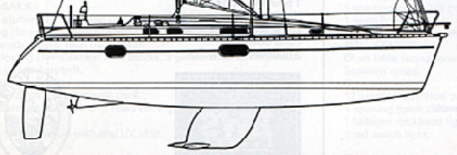
The Beneteau Oceanis 351 and Oceanis 352 represent a pivotal evolution in modern production yacht manufacturing during the 1990s. Designed by the naval architecture firm Berret-Racoupeau (led by Jean Berret) in collaboration with interior designer Armel Briand, these sister models were engineered to optimize interior living volume, initial form stability, and cost-effective modular assembly. Introduced in 1993, the Oceanis 351 succeeded the Philippe Briand-designed Oceanis 370, establishing a design language focused on maximum waterline length and wide aft beam. In 1997, Beneteau introduced the Oceanis 352, which retained the same underwater hull mold and rig geometry as the 351 while implementing targeted structural, deck, and interior joinery refinements until production concluded in 1999.
Both models were manufactured at Beneteau’s primary production facilities in France and at its North American facility in Marion, South Carolina. The developmental trajectory of both models was heavily influenced by operational feedback from high-utilization charter operations, particularly within The Moorings charter fleets. This continuous feedback loop enabled Beneteau to systematically refine the vessel’s fiberglass internal structural grid, deck ergonomics, and line-handling systems across both production runs.
Structural Architecture and Construction Methodologies
The structural hull of both the Oceanis 351 and 352 is built using solid, hand-laid glass-reinforced plastic (GRP) below the waterline, reinforced with unidirectional rovings to absorb operational loads. To guard against osmotic blistering, Beneteau incorporated the patented Beneteau Watershield System (BWS) into the layup schedule. This manufacturing process integrates a specialized vinylester resin layer into the outer hull laminate, creating a chemical barrier behind the gelcoat prior to the application of standard orthophthalic polyester layers.
Primary structural stiffness and load distribution are achieved through an internal fiberglass grid system, frequently referred to as a matrix or hull liner. This pre-molded fiberglass pan is bonded directly to the inner surface of the solid hull skin using structural polyester adhesive pastes. The matrix serves as the foundation for the entire vessel, distributing concentrated loads from the keel bolts, mast step compression post, engine mounts, and chainplates across the hull laminate. Interior joinery, structural bulkheads, and modular sub-assemblies (such as the head and galley units) are keyed into pre-formed channels within this internal grid and structurally glued in place.
The load path architecture transfers rigging forces directly into this internal structure. Downward thrust from the deck-stepped mast passes through a compression post onto the central matrix frame directly above the keel stub. Tensile loads from the standing rigging pass through deck chainplates, which are anchored via adjustable stainless steel tie rods connected directly to the outboard longitudinal stringers of the internal grid. This configuration creates a rigid closed-loop load distribution system that minimizes deck deflection under high sail loads.
The deck structure is constructed as a sandwich laminate cored with end-grain balsa, providing elevated flexural rigidity, thermal insulation, and acoustic damping while minimizing weight. In zones subjected to high localized hardware loads—such as cleat mountings, genoa tracks, and winch bases—the balsa core is substituted with solid GRP laminates. The hull-to-deck junction utilizes an inward-turning hull flange. During structural mating, the deck is bedded onto the flange using a high-tack polyurethane structural adhesive (such as 3M 5200) and mechanically secured with sheet-metal screws. The connection is permanently bound by stainless steel through-bolts that simultaneously clamp an anodized aluminum toerail around the perimeter, protecting the underlying joint from impact damage during docking.
Engineering Vulnerabilities and Structural Inspection Protocols
While the internal matrix bonding system offers production efficiency and excellent structural rigidity under standard operating conditions, it introduces specific structural vulnerabilities over extended service lives. The mechanical integrity of the vessel depends on the continuity of the adhesive bond line between the fiberglass matrix and the solid GRP hull laminate.
Hard groundings or heavy impacts to the keel place extreme leverage on the matrix structure. In a grounding event, the downward and aft leverage of the keel forces the aft trailing edge of the keel stub upward into the hull while pulling the forward foot downward. This movement subjects the structural adhesive paste to high shear stress. Adhesion failure along the matrix border leads to localized debonding. Once debonding occurs, the hull laminate flexes independently of the grid under sail loads, causing progressive delamination around the bilge sump, engine beds, and transverse floors.
Marine surveyors and prospective buyers evaluating these vessels must execute focused non-destructive evaluation protocols around the grid structure:
- Acoustic Percussion Testing: Tapping with a phenolic hammer along the bilge matrix bonding borders, floors, and stringers to identify hollow tones that indicate void spaces, adhesive cracking, or liner debonding.
- Keel-to-Hull Interface Inspection: Examining the exterior keel stub for transverse hairline cracking (“smile lines”) at the forward and aft joints, which may correlate with internal matrix displacement.
- Freeze-Thaw Matrix Evaluation: Inspecting the matrix channels and limber holes for standing water damage; trapped bilge water exposed to freezing conditions can expand within unsealed matrix voids, mechanically separating the liner pan from the hull laminate.
Hydrodynamic Specifications, Ratios, and Comparative Data
The underlying hull geometry of the Oceanis 351 and Oceanis 352 is identical, as both models share the same Jean Berret hull mold. Variations in published specifications across production years stem primarily from differences in factory options, displacement measurement methodologies, ballast choices (shoal wing versus deep fin), fuel and water tank material specifications, and regional equipment packages.
| Technical Parameter | Oceanis 351 Specification | Oceanis 352 Specification | Architectural & Hydrodynamic Implication |
| Naval Architect | Jean Berret / Armel Briand | Berret-Racoupeau / Armel Briand | Identical hull dynamics across both models. |
| Production Years | 1993 – 1997 | 1997 – 1999 | 352 represents a late-decade production evolution. |
| Length Overall (LOA) | 34′ 9″ – 35′ 0″ | 35′ 0″ – 35′ 7″ | Extended plumb bow maximizes dynamic waterline length. |
| Waterline Length (LWL) | 30′ 5″ – 31′ 1″ (9.28 – 9.48 m) | 31′ 1″ (9.47 m) | |
| Maximum Beam | 12′ 5″ – 12′ 6″ (3.80 m) | 12′ 5″ – 12′ 6″ (3.81 m) | Wide beam carried aft provides initial form stability. |
| Draft (Shoal / Wing) | 5′ 0″ (1.53 m) | 4′ 11″ – 5′ 0″ (1.50 – 1.52 m) | Winglets generate lift while maintaining shallow access. |
| Draft (Deep Fin) | N/A (Factory Standard Wing) | 5′ 11″ (1.80 m) | A fin configuration optimizes upwind pointing. |
| Displacement | 11,684 lbs (5,300 kg) | 12,000 – 14,774 lbs (5,443 – 6,702 kg) | Categorized as light-to-moderate displacement. |
| Ballast Weight | 3,748 lbs (1,700 kg) | 3,682 – 3,750 lbs (1,701 kg) | |
| Fuel Capacity | 24 – 26.4 gal (90 – 100 L) | 20 – 26.4 gal (76 – 100 L) | Provides adequate motoring endurance for coastal hops. |
| Freshwater Capacity | 106 gal (400 L) | 53 – 106 gal (200 – 400 L) | Dual rigid plastic tanks maintain long cruising autonomy. |
| Standard Engine | Yanmar 3GM30 / Perkins M30 | Yanmar 3GM30F (27-29 hp) | Direct shaft drive coupled with a standard stuffing box or shaft seal. |
Analyzing the core naval architectural ratios reveals the stability profiles and handling traits of this hull platform:
| Naval Architectural Ratio | Calculated Value | Operational & Performance Interpretation |
| Sail Area / Displacement (SA/D) | 17.0 – 19.4 | Indicates a moderately powered rig balance. Provides efficient speed in light-to-moderate breeze without overstressing shorthanded crews. |
| Displacement / Length (D/L) | 178.4 | Establishes a light-medium displacement profile. Allows quick acceleration off the wind and easy surfing down swells. |
| Ballast / Displacement (B/D) | 31.2% | Reflects reliance on form stability (hull width) over heavy deep ballast to resist heel forces. |
| Brewer Comfort Ratio | 19.9 | Demonstrates a relatively lively motion in a seaway. The vessel responds rapidly to wave crests, making it ideal for coastal passages rather than high-latitude ocean survival. |
| Capsize Screening Formula (CSF) | 2.19 | Exceeds the standard offshore threshold of 2.0, confirming the vessel’s primary classification for coastal, cross-channel, and island passage-making. |
The hydrodynamic behavior under sail is governed by the hull’s beam distribution. With a maximum beam of 12 feet 6 inches carried well aft, the vessel exhibits high initial form stability, stiffening rapidly up to approximately 15 degrees of heel. However, if pushed beyond 20 degrees of heel, the wide beam elevates the windward quarter and lifts the single centerline spade rudder partially out of the water. This reduces rudder surface immersion, triggering a tendency to round up into the wind if the mainsail is over-canvased.
To optimize tracking and avoid broaching in heavy wind gusts, sailors must adopt a proactive reefing regimen.
Rigging, Handling, and Mechanical Systems
Both models feature a masthead sloop rig configured with an anodized aluminum deck-stepped Z-Spar mast supported by double, slightly swept spreaders. The double spreader layout provides lateral column stiffness while eliminating the requirement for complex running backstays. All standing rigging consists of 1×19 stainless steel wire, terminated with swaged fittings, and anchored to deck chainplates.
Sail management is designed around shorthanded efficiency. Halyards, reefing lines, outhauls, topped lifts, and mainsheet controls are routed aft beneath a secondary cabintop deck cover to Spinlock rope clutches and Lewmar winches flanking the companionway. Genoa tracks are positioned inboard on the coachroof deck rather than along the outer side decks. This placement accomplishes two objectives: it opens an unobstructed walkway along the side decks for forward movement and allows tighter sheeting angles for improved upwind pointing capability.
Most Oceanis 351 and 352 units left the factory equipped with in-mainsail furling systems paired with a forestay roller furler handling a 140% genoa. The mainsheet traveler is mounted on the coachroof forward of the companionway hatch. While this mid-boom sheeting arrangement clears the cockpit sole for seating and allows for large biminis and dodgers, it increases mechanical leverage loads on the boom and reduces fine-grain traveler control from the helm position.
Auxiliary power is provided by a 3-cylinder Yanmar 3GM30F marine diesel engine generating 27 to 29 horsepower. Power is transmitted through a traditional direct-drive stainless steel propeller shaft, operating via a bronze strut and a rubber cutless bearing. The engine installation burns approximately 0.8 to 1.0 gallons per hour at a smooth cruising speed of 6.0 to 6.5 knots at 2,400 RPM, achieving a top motoring speed of more than 7knots at wide-open throttle.
The choice of propeller significantly impacts sailing performance. Hydrodynamic drag tests demonstrate that a standard locked three-blade fixed propeller generates between 45 and 50 pounds of resistive drag while under sail. Converting to a folding or feathering propeller reduces underwater drag to 20–25 pounds, yielding an immediate performance gain of 0.5 to 0.75 knots under sail in light-to-moderate wind conditions.
Accommodation Layouts and Interior Ergonomics
The interior design across both the 351 and 352 emphasizes natural overhead lighting, ventilation, and maximized standing headroom. Beneteau configured both models in two primary accommodation layouts designed for private owners or charter operators.
| Functional Area | Owner’s Version (Two-Cabin Layout) | Charter Version (Three-Cabin Layout) |
| Aft Accommodation | Single expansive transverse master berth (2.00 m x 1.90 m) stretching beneath the cockpit. | Symmetrical twin quarter cabins port and starboard (2.00 m x 1.20 m berths). |
| Head & Shower | Large head compartment to starboard featuring a separate molded shower stall and wet locker. | Compact single head compartment to clear structural space for the port quarter cabin. |
| Forward Cabin | Private double V-berth with standing headroom, hanging locker, and changing seat. | Identical private double V-berth with overhead ventilation hatch. |
| Main Saloon | Semi-circular settee surrounding a convertible mast-mounted dining table to starboard. | Identical semi-circular settee layout with convertible settee berth capability. |
| Galley Layout | L-shaped gourmet galley positioned immediately to port of companionway steps. | Linear or modified L-shaped galley adjacent to the companionway. |
| Nav Station | Dedicated forward-facing chart table with electrical distribution panel to port. | Compact chart table integrated into the forward end of the port settee berth. |
In both versions, the main saloon achieves an average standing headroom of 6 feet 3 inches. The central dining table is mounted on a mechanical collar surrounding the steel compression post. By releasing the locking pin, the table slides down the post to align with the settee cushions, creating a large double berth for additional guests.
The L-shaped galley is optimized for offshore meal preparation while underway:
- Storage and Sinks: Dual deep stainless steel sinks equipped with pressurized hot and cold mixing faucets, situated near the vessel’s centerline for proper drainage on either tack.
- Refrigeration: A top-loading 130-liter insulated icebox, typically fitted with a 12V DC compressor.
- Cooking System: A gimbaled two- or three-burner propane stove with an integrated oven, secured by safety bars.
- Ventilation: A dedicated opening deck portlight located directly above the stove, providing heat dissipation without venting fumes into the main saloon.
Model Evolution: Structural and Architectural Distinctions
Although built upon the exact same hull mold, the transition from the Oceanis 351 to the Oceanis 352 in 1997 introduced distinct architectural, structural, and cosmetic refinements. These modifications were implemented to modernize the model line and address feedback from cruising owners.
OCEANIS 351 (1993–1997) OCEANIS 352 (1997–1999)
Matte Mahogany / Early Stains • High-Gloss Varnished Cherry
• Standard Side Portlights • Added Coachroof Skylights
• Traditional Helm Pedestal • Integrated Console & Instrument Pods
• Removable Transom Bench • Hinged Fold-Out Helm Seat
Interior Joinery and Cabinetry
The Oceanis 351 featured traditional matte-finished mahogany interior joinery. The Oceanis 352 updated the interior aesthetics to high-gloss varnished cherry wood veneers. Cabinetry corners were updated with rounded solid-wood capping, and door latches were upgraded to heavy-duty push-button hardware.
Illumination and Ventilation Systems
To increase interior ambient lighting, the Oceanis 352 incorporated additional fixed coachroof skylights and redesigned opening side ports. This modification eliminated the dark aesthetic common in early 1990s mid-size production yachts, allowing direct sunlight to enter the galley and navigation station.
Cockpit and Helm Console Ergonomics
The Oceanis 351 utilized a traditional stainless steel pedestal guard with basic compass housing. The Oceanis 352 introduced an integrated fiberglass helm console. This console featured built-in folding table leaves, a central insulated icebox, dedicated instrument pods for Raymarine/Garmin navigation displays, and a protective clear Plexiglas shield over the lower Yanmar engine control panel.
Transom Boarding Access
Access to the sugar-scoop swim platform on the Oceanis 351 required manually unclipping life-lines and removing a removable fiberglass helm seat. The Oceanis 352 introduced a hinged, fold-out helm seat that swings open on stainless steel pivots, providing walk-through access to the transom platform, swim ladder, and freshwater cockpit shower.
Marine Survey Protocol and Buyer Evaluation
Prospective buyers evaluating pre-owned Oceanis 351 or 352 models should ensure their marine surveyor incorporates a rigorous, model-specific inspection regimen. Given the age of these vessels, structural integrity, mechanical systems, and rig security represent the primary areas of financial and operational risk.
The following survey protocols should be executed prior to acquisition:
- Grid Bond Lines: Thoroughly inspect the bilge matrix grid under the floorboards using hammer sounding and moisture metering. Look for signs of stress cracking, bonding paste failure, or standing water separation around the forward and aft keel bolt clusters.
- Keel Fasteners: Inspect the stainless steel keel bolts, backing plates, and structural washers for crevice corrosion. Ensure that backing plates are not crushing into the GRP matrix floors due to past over-torquing or structural flexing.
- Rigging Tie Rods and Chainplates: Inspect the lower turnbuckles and stainless steel tie rods inside the saloon lockers. Check for signs of water entry around the deck chainplate penetrations, as this can degrade the cored-deck sandwich laminate.
- Engine Mount Alignment: Verify that all four Yanmar engine mounts are structural and secure. Inspect for missing adjustment locking nuts, which can cause severe drive shaft misalignment, cutless bearing vibration, and stuffing box leakage.
- Through-Hull Fittings and Valves: Inspect all original brass or bronze skin fittings and gate valves below the waterline. Original valves should be evaluated for dezincification and replaced with modern marine-grade bronze or composite ball valves.
Conclusion
The Beneteau Oceanis 351 and Oceanis 352 remain benchmark examples of successful 1990s production boatbuilding. By pairing a hydrodynamic hull form designed by Jean Berret with modular internal manufacturing techniques, Beneteau created a platform that delivers spacious accommodations, comfortable coastal seakeeping, and predictable sailing performance.
For sailors deciding between the two models, the choice largely balances initial acquisition cost against interior refinement. The Oceanis 351 provides a cost-effective pathway into a capable 35-foot cruiser with identical underwater performance to its successor. The Oceanis 352 offers a more contemporary interior aesthetic, superior natural lighting, and improved ergonomics at the helm console. Provided that a thorough marine survey confirms the structural integrity of the internal grid bond, both models continue to serve as highly reliable cruising platforms on the international brokerage market.